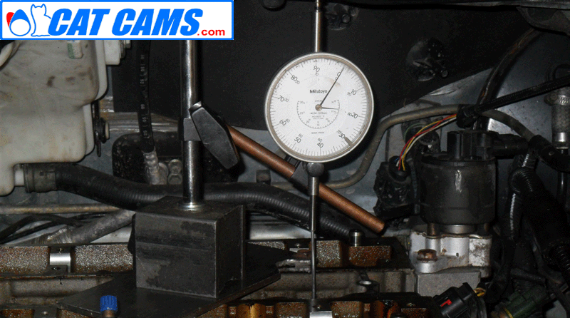
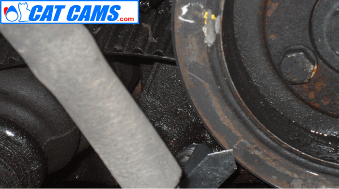
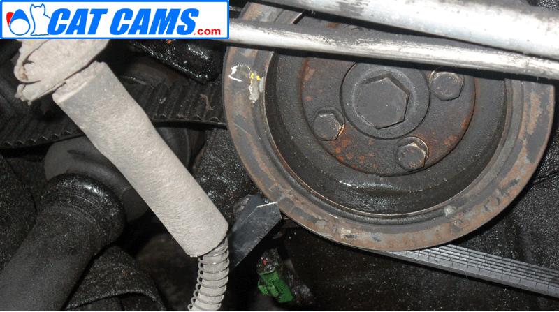
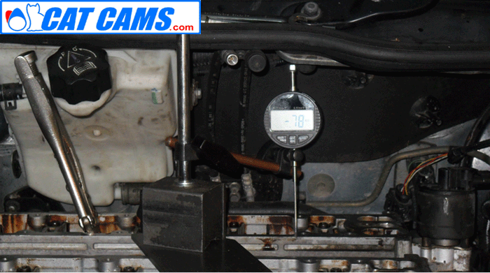
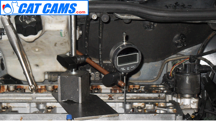
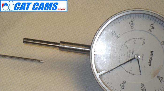
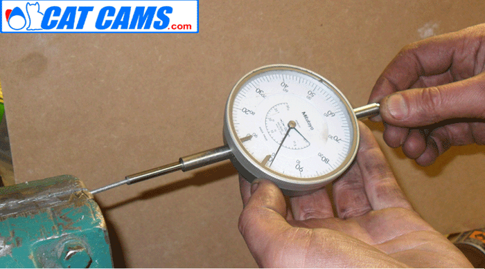
Cam TimingSetting the cam timing of an engine using the Lift @ TDC values rather than the peak angle is a much simpler and faster way of correctly timing the camshafts. With a Single cam engine, timing via peak angle is relatively easy since the relationship between the inlet and exhaust lobes is fixed by the camshaft. However, trying to set the timing on a twin cam or quad cam engine is far more difficult as you have to have a starting point so none of the valves are accidentally bent while turning the engine over. As we need a setting point for the cams, it makes much more sense to actually time the cams at Top Dead Center and avoid having to move the crankshaft at all. As we know the full details of the camshaft, its a simple matter to work back from the peak lift position to find the lift when the crank is at TDC. First we need to find the true top dead center position of the crankshaft. As the piston 'Dwells' at TDC we need to take 2 measurements while the piston is moving and then find the center point of these (See Pics 1-3). If possible, its much safer to have the camshafts removed to do this!! If thats not possible pay careful attention to which valves are open and which pistons are coming up the bore!! First find the true TDC of the piston by marking the crank pulley with the piston 0.3mm either side of TDC. Here's the first mark on the crank pulley. Note the pointer which is simply a peice of thin steel bent to shape and secured to the block via a bolt for the front cover. You can also attach a Timing disc to the pulley if you wish. Superglue is very handy for temporary fitment but it wont hold the disc on when the engine is running! Now you can see both the marks (0.3mm either side of TDC) and the middle of the center marks is the true To find the center just measure the distance between the mark with a Vernier, halve it and My marks were not 100% exact so I have 2 lines in the middle but they are close enough to position Now you have this be careful not to move the pointer!! Now we have the True TDC position and have moved the pistons down the bore we can fit the cams and (in this case 0.78mm @ TDC for the exhaust). With this type of cam carriers its not possible to use a piece of paper under the bearing to hold the cam in position. With the exhaust in the correct position next set the inlet cam. Note the TIG welding rod extensions for the dial gauge can be bent to make it easier to get onto the follower/ Also note that the dial gauge needs to be at the same angle as the follower bore to ensure the correct reading. Now we have the true TDC position, turn the crank so the pistons are out of the way of any possible valve contact(on a 4 cylinder engine you can turn the crank 90 degrees so the pistons are level half way up the bore) Next, make sure the vernier pulleys are loose and move freely. Start with the inlet cam, take the lobe that is just opening the valve (cyl 1 or 4 on a 4 cyl engine). Rotate the cam so the valve is closed and the follower is on the base circle. Zero the dial gauge and then turn the cam so the valve is open the correct amount (as indicated on the data sheet), Pic 4 Remember, with mechanical profiles you need to subtract the valve clearance from the lift@tdc figure. Next move the dial gauge to the exhaust camshaft and repeat the above procedure (pic 5) Now we have the camshafts set in the correct position we can carefully bring the crankshaft back up to the TDC position we found earlier. Make sure you are bringing the correct cylinder up the bore. On a 4 cylinder engine, the valves on cylinders 1 and 4 are safe but cylinder 2 and 3 will have the valves open. If you feel any resistance then stop and find out what the problem is. Its VERY easy to bend valves when turning the crank!! Fit the cambelt and tension it with the vernier pulleys still loose so the cams and crank stay in position. Next tighten the pulleys and turn the crank through at least 720 degree's to bring it back to its original position. Double check the reading on the dial gauge (which should still be on the exhaust lobe). Usually you will have to slightly correct this, make sure you always turn the engine in the direction of normal rotation to keep the tension on the correct side of the cambelt. Now move the dial gauge back to the inlet side and double check the lift @ TDC figure. After correction make sure you turn the engine over to double check, its not unusual to have to repeat this a couple of times on some engines but your patience will pay off in having the cam timing absolutely perfect. To lock a camshaft in position, place a small piece of paper under one of the cam caps. Dont forget to remove it afterwards!! To extend a dial gauge, remove the tip and use 3mm Aluminium TIG welding rod as an extension. Grind a point onto the end and it will screw into the end of the gauge. These can be easily bent around camshafts, made long enough to reach to the piston crown etc. See pics 6 & 7 Use 3mm Aluminuim Tig Filler rod to extend the dial guage. Simply unscrew the ball from the end of the gauge, grind a point onto the filler rod and screw it in place Masterclass: When the lift @ TDC values are very small its easier to measure the lift before BDC (this is very useful for engine with Variable cam timing or very short duration profiles. If you need the Lift BBDC figures just ask. |